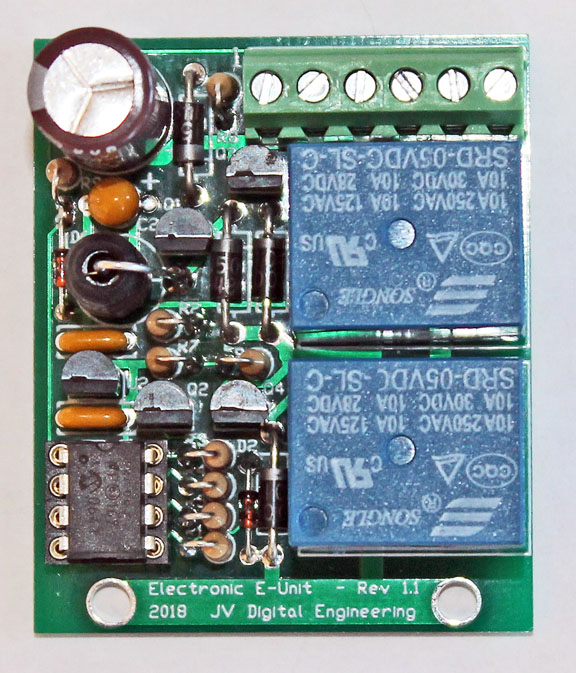
Electronic E-Unit Assembled PCB
JV Digital Engineering Home Page
Electronic E-Unit Assembly Notes
11/11/18
The Electronic E-Unit should be a relatively easy PCB to assemble. Assembly requires experience working with small components, and also the ability to correctly identify component values. A low-wattage soldering iron with a 1/16" tip is recommended. Care must be taken to not overheat the semiconductor devices.
BEFORE ASSEMBLY
A few people have had trouble identifying components. You will need a magnifier to read the some of the part numbers. I recommend sorting out all components before soldering any onto the board. Be sure you have correctly identified the diodes before you begin installing them.
PRINTED CIRCUIT BOARD ASSEMBLY:
Please read these Detailed Assembly Instructions before beginning actual assembly to avoid any problems. Also, please refer to the parts list, board layout, and high-resolution photograph of the assembled board while assembling your own unit:
Electronic E-Unit Board Layout
Electronic E-Unit Board Photograph
Do not try to assemble the Electronic E-Unit with a high wattage soldering iron having a tip larger than 1/8". A variable temperature iron with a 1/16" tip works well. I recommend installing all diodes and other components that mount flush to the board first, followed by the DIP socket. Many components stand on end to save space. Work your way up to larger and larger components. Leave the inductor and electrolytic capacitor for last.
Things to watch out for:
1) Be careful of the diode polarity Other components may be damaged if the diodes are not installed correctly.
2) C2 is a polarized tantalum capacitor. Be very careful to get the polarity correct. The positive (+) lead on C2 is marked "+", and may also have a long vertical line.
3) D2 was eliminated and R1 increased to 1 meg to reduce sensitivity to electrical noise from brush arcing in high power motors.
4) All leads should be cut short – certainly no longer than 1/8” above the board.
RECOMMENDED ASSEMBLY ORDER:
D6 (zener)
D1, D4, D5 (1N4004)
D3 (SB150)
DIP socket for U1
C3, C4
C2 (Be sure of polarity)
R1, R3, R4, R5
R2, R6, R7, R8, R9
Q1
Q2, Q3, Q4
U2
Terminal Block J1 (Wire entry faces board edge.)
RLY1, RLY2 (Push down firmly to be sure they are fully seated.)
L1
C1 (Negative "-" terminal faces board edge.)
Plug in the PIC microcontroller U1 with the notched end facing U2 & C4.
INTERWIRING & FINAL ASSEMBLY:
First check that all components are installed in the proper locations and that all diode and capacitor polarities are correct.
After checking your solder connections and making sure all leads are snipped short, install the PCB onto your engine and connect the leads as specified below:
1 - Optional lock-out switch to chassis frame
2 - Ground to chassis frame (or mount with metal bracket to chassis frame)
3 - Track AC power in
4 - Motor armature terminal 1
5 - Motor armature terminal 2
6 - Motor field
TEST & OPERATION:
Apply track power and the engine should begin running. Whether it starts off in fowared or reverse depends on the order of the motor terminals. But from this point on it should always increment to the next state regardless of how long power has been interrupted, just like the mechanical version. Connecting the lock-out switch terminal to the chassis frame will lock the unit in its prior state.
Please contact me if you have any questions at: jeff@jvde.us
If you don't receive a response within 24 hours, try: xtbjeff@gmail.com
Electronic E-Unit Assembled PCB
JV Digital Engineering Home Page