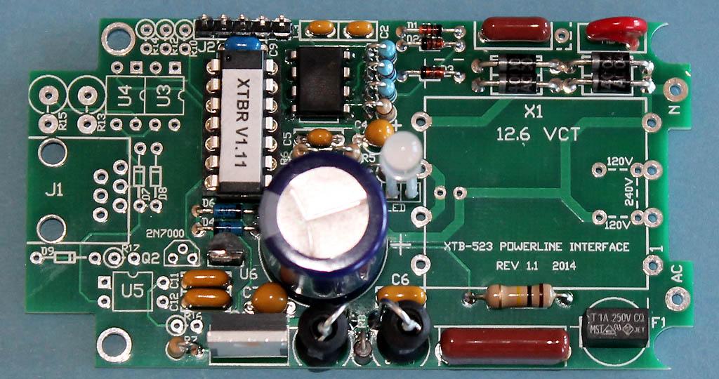
XTBR Assembled on the XTB-523 PCB before installing transformer X1
NOTE: The missing components on the left side are for the serial port.
XTBR Assembly Notes
08/20/15
Please check for the latest version before beginning assembly.
The XTBR has a densely populated circuit board. Assembly requires experience working with small components, and also the ability to correctly identify component values. A low-wattage soldering iron with a 1/16" tip is recommended. Care must be taken to not overheat the semiconductor devices.
BEFORE ASSEMBLY
A few people have had trouble identifying components. The zener diode has been packaged with the other semiconductors to help identify it. It is best to keep it packaged until you are ready to install it. You will need a magnifier to read the some of the part numbers. Be sure you have correctly identified ALL the diodes before you begin installing them. I also recommend sorting out the capacitors and resistors before soldering any onto the board. Be careful to correctly identify the 10K and 47K 5% resistors (orange 3rd band). The 1% resistors are blue and have an additional color band, so be careful identifying them.
PRINTED CIRCUIT BOARD ASSEMBLY:
The XTBR shares either the XTB-232 or the XTB-523 PCB. The serial port components are left unpopulated. Although the values are identical for both boards, some of the part numbers are different. Please read these Detailed Assembly Instructions before beginning actual assembly to avoid any problems. Also, please refer to the parts list, board layout, and high-resolution photograph of the assembled board while assembling your own unit:
Do not try to assemble the XTBR with a high wattage soldering iron having a tip larger than 1/8". A variable temperature iron with a 1/16" tip works well. I recommend installing all diodes and resistors that mount flush to the board first, followed by U1 and the DIP socket for U2. Many components stand on end to save space. Work your way up to larger and larger components. Leave the electrolytic capacitor, transformer, and LED for last. The XTB-232 Board Photograph shows the board before the transformer is mounted. The two boards are slightly different, but components to the left of the microcontroller (U2) are left unpopulated in the XTBR.
Things to watch out for:
1) The XTBR is a tight fit in the Polycase. The board mounts between the standoffs at the transformer end to give enough clearance for the transformer to just squeeze in. The transformer must be mounted flush to the circuit board, and any required jumpers placed on the underside of the board.
2) A dual-primary transformer may be supplied with the XTBR. That can be identified by it having 4 pins on both sides. A dual-primary transformer requires two short jumpers to be installed on the reverse side of the board to connect the primaries in parallel for 120V operation. The connections are diagramed on the silkscreen. Cut-off component leads can be used for both of the short jumpers. Be sure to cut these leads flush with the top surface of the board so they don’t interfere with the transformer.
3) There is no extra clearance between the transformer and the top cover. The transformer must be firmly seated to the PCB before soldering it down. If you have installed jumpers for a dual primary transformer, they must be snipped flush with the top of the PCB so they don't contact the transformer. Depending on the transformer manufacturer, the pin numbers may be labeled on the bobbin near the pins, or there may be a mark at pin 1. Pin 1 should be inserted into the pad adjacent to the fuse.
4) C4 and C7 are polarized tantalum capacitors. Be very careful to get the polarity correct. The positive (+) lead is marked "+", and may also have a long vertical line.
5) The LED is mounted full-length with sleeving over both pins. The parts kit should contain a 2" length of clear sleeving. Cut that exactly in half and trim slightly so the shortest lead extends just through the circuit board. The longest lead goes into the + pad. When the cover is installed, the LED should slip into the clear lens snapped into the cover.
6) J2 is a programming header that is not normally needed for the kit version.
RECOMMENDED ASSEMBLY ORDER:
D1, D2 (1N4148)
D3 (zener)
D4, D5, D6 (BAT43)
D8-D11 (D10-D13) (1N4002-4)
NOTE: these are D10-D13 on the XTB-523 PCB
R9
Add 120V transformer jumpers on back if transformer has a dual primary (8 pins)
NOTE: snip jumpers flush with top of board before installing transformer
U1
U2 socket
C2, C3 (330pF)
C5, C9
C6, C11, C12
F1
R1, R2, R3, R4, R5, R6, R7, R10 (R11) (R1-R3 are 1%)
NOTE: 220 ohm R10 is R11 on the XTB-523 PCB
NOTE: 220 ohm R10 (R11) should look like all the other 1/4W carbon film resistors
NOTE: no 1/4W resistors except the R8 carbon composition should be left
C4, C7 (C7 is 35V & be sure of polarity)
C1, MOV
J2 (5-pin header)
C8
R8
L1, L2
U6 (78L05 - small regulator that looks like a transistor)
Q1 (metal tab facing board edge)
C10 (be sure of polarity)
X1 Transformer (pin 1 at corner near the fuse)
LED (cut sleeving in half, insulate leads, mount full height with longer lead at +)
Plug U2 into socket (be sure the notched end faces J2)
XTBR Assembled on the XTB-523 PCB before installing transformer X1
NOTE: The missing components on the left side are for the serial port.
INTERWIRING & FINAL ASSEMBLY:
IMPORTANT: The Polycase base must be modified to prevent conflict between the circuit board and the AC plug ground pin. That extension will be removed from bases shipped with XTBR kits. If your base has not been modified, use a rotary tool with a small cutoff disc to remove the internal extension of the ground pin so that it is flush with the plastic base. Also cut off the ground tab even with the plastic case since that is not used. It is unfortunate that Polycase does not make a version of this case with a 2-prong plug.
Cut the wire into two 2" lengths, strip 1/4 of insulation from each end and tin. Solder one end of each wire to the top of the PCB at locations marked AC and N, and trim the excess flush with the bottom of the board.
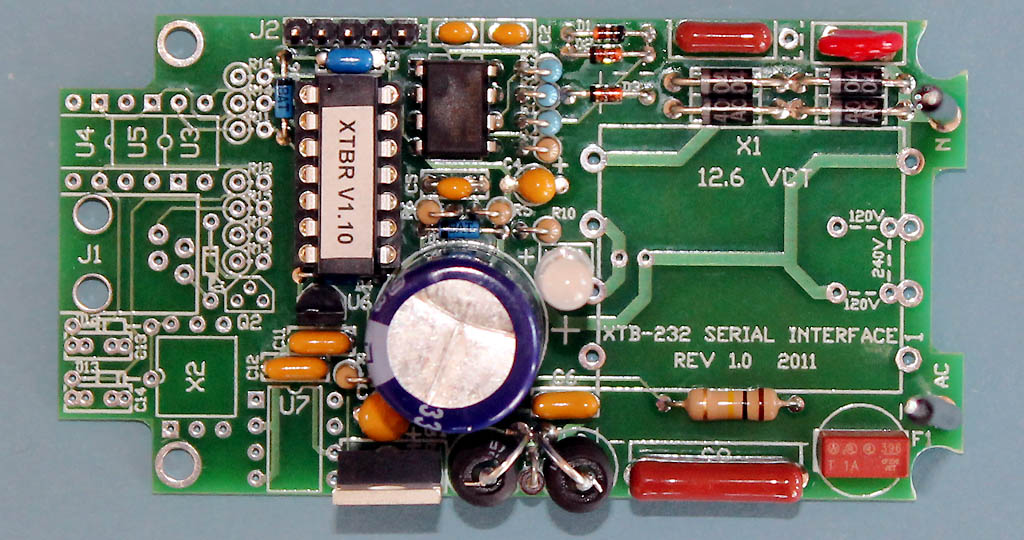
Completed XTBR PCB assembly using XTB-232 PCB
Carefully inspect the board for any poor solder connections. Verify all diodes and polarized capacitors are installed in the correct orientation. Mount the board to the base using 4 screws. Since the board sits between the mounting standoffs at the transformer end, use the two insulating washers to hold the board in place.
Connect the two free wires to the adjacent AC plug prongs, and solder.
Make sure the LED is exactly vertical so it will slip into the lens when the cover is attached. If the case doesn't fit over the transformer, the edges of the bobbin can be rounded slightly with a file or wire cutter to fit under the case. (Be careful not to get too close to the windings.) Attach the cover with the 4 black self-tapping screws.
Add the XTBR label to the flat area of the base.
TEST & OPERATION:
As a final check before applying power, verify the resistance between the two plug prongs is about 400 ohms. If it reads much lower, the transformer may have been installed backwards.
To verify your XTBR is operational, plug it into an AC outlet. The LED should glow dim green and briefly flash red about a second after being plugged in as it transmits "P_Status_ON. Then send a command from any X10 transmitter, and the LED should flash brighter green and red as it receives and repeats that command. The LED will just flash red for commands sent from a nearby transmitter as the XTBR boosts both halves of the X10 doublet. Multiple red flashes indicate various error conditions. If the LED doesn't light up at all, or it flashes red when not transmitting, then it is likely something is wired wrong.
Now that your XTBR is operational, just plug it into a wall outlet near your distribution panel, and it will repeat any X10 commands received over the powerline to a much higher level.
Please contact me if you have any questions at: jeff@jvde.us
If you don't receive a response within 24 hours, try: xtbjeff@gmail.com
JV Digital Engineering Home Page
[XTB & XTB-II/R Overview] [XTB Home Page] [XTB Ordering Info] [X10 Troubleshooting Info]