JV Digital Engineering
Updated 11/14/09
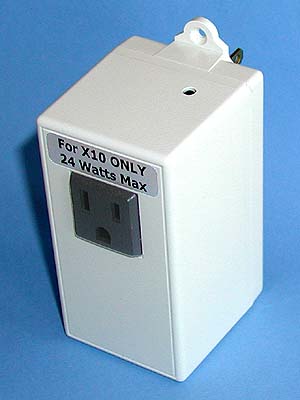
The XTB was designed to improve the reliability of X10 automation systems. It simply plugs between any X10 control module and the wall socket to amplify the X10 signals from that transmitter. The XTB has a 6-watt transformer power supply, and will produce a much stronger signal than X10 transmitters with inexpensive transformerless supplies. Its high-power FET driver can output over 20Vpp onto the AC line. The XTB also includes an amplifier to boost low-level X10 return signals. The XTB can be used with most X10 transmitters, such as the CM15A, CM11A, RR501, TW523 or Maxi-Controller. It will not work with Insteon products, and is not compatible with the PowerLinc 1132B or Lynx-PLC.
A single XTB located a short run from the main distribution panel can provide strong X10 signals throughout a large home. A good passive coupler should be installed near the distribution panel when X10 devices are used on both phases. An enhanced repeater version, called the XTBR, is also available. The XTB is intended to boost the output of a single X10 transmitter. For installations with multiple transmitters, either the XTBR or the two-phase XTB-IIR are more cost effective solutions.
With a XTB near our main distribution panel, I measured 2.5V or better signal levels on most circuits throughout our house. One “problem” circuit containing a large number of X10 receivers and transmitters came up from 100mV to about 1V. Another circuit at the far end of the house read 100mV when feeding a signal-sucking UPS, and 1V with that UPS isolated by a filter. That shows the large impact a single electronic device can have on X10 signal levels. But it also shows the XTB can get an acceptable signal level to the end of a long cable run even with a major signal sucker on that circuit.
The X10 input receptacle on the XTB is rated for 24 watts resistive. More than one device plugged into it will degrade the return signal level. It is important not to exceed the 24-watt limit to prevent damage to internal components. While a typical X10 transmitter consumes less than 3 watts, its load is reactive. To remain safely within the rating, no more than two X10 transmitter loads should be powered by the XTB.
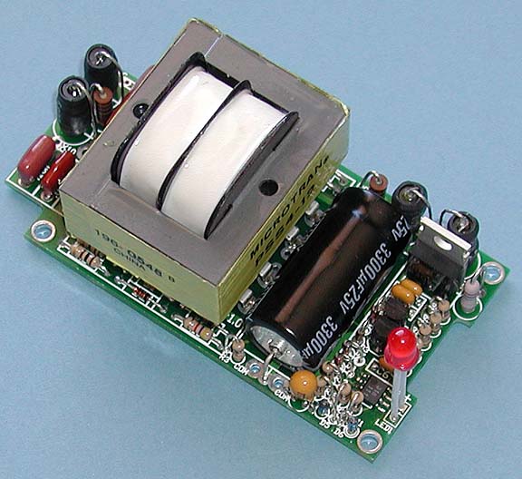
The XTB is available as a bare printed circuit board, or a complete parts kit. Assembly requires an understanding of component values and color codes, and should only be attempted by someone skilled at soldering high-density printed circuit boards with small surface-mount components. An assembled and tested unit is available upon receipt of a signed Liability Waver.
Click here for prices and ordering information for the XTB and related products.

Please contact me if you have any questions at: jeff@jvde.us
If you don't receive a response within 24 hours, try: xtbjeff@gmail.com
JV Digital Engineering Home Page
[XTB & XTB-II/R Overview] [XTB Home Page] [XTB Ordering Info] [X10 Troubleshooting Info]