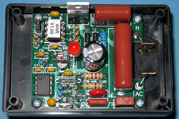
Assembled XTB-ANR
JV Digital Engineering Home Page
[XTB & XTB-II/R Overview] [XTB Home Page] [XTB Ordering Info] [X10 Troubleshooting Info]
XTB-ANR Assembly Notes
10/25/12
Please check for the latest version before beginning assembly.
The XTB-ANR should be a relatively easy PCB to assemble. Assembly requires experience working with small components, and also the ability to correctly identify component values. A low-wattage soldering iron with a 1/16" tip is recommended. Care must be taken to not overheat the semiconductor devices.
BEFORE ASSEMBLY
A few people have had trouble identifying components. The zener diodes are packaged with the other semiconductors to help identify them. It is best to keep them packaged until you are ready to install them. You will need a magnifier to read the some of the part numbers. Be sure you have correctly identified ALL the diodes before you begin installing them. I also recommend sorting out the capacitors and resistors before soldering any onto the board.
PRINTED CIRCUIT BOARD ASSEMBLY:
Please read these Detailed Assembly Instructions before beginning actual assembly to avoid any problems. Also, please refer to the parts list, board layout, and high-resolution photograph of the assembled board while assembling your own unit:
Do not try to assemble the XTB-ANR with a high wattage soldering iron having a tip larger than 1/8". A variable temperature iron with a 1/16" tip works well. I recommend installing all diodes and other components that mount flush to the board first, followed by DIP integrated circuits and the DIP socket for U2. Many components stand on end to save space. Work your way up to larger and larger components. Leave the electrolytic capacitor and LED for last.
Things to watch out for:
1) Be careful of the diode polarity - especially D6 and D7. Other components will be damaged if those diodes are not installed correctly.
2) The 1% resistors are blue. They follow the standard color code, but there is a 3rd value digit, and the tolerance band is brown for 1%.
3) The 220uH inductor L1 may be blue or green, and looks like a 1/2W resistor. It can be identified by its resistance is being about 5 ohms.
4) C7 and C9 are polarized capacitors. Be very careful to get the polarity correct. The positive (+) lead on C7 is marked "+", and may also have a long vertical line.
5) The LED must be mounted at the correct height to slip into the lens on the cover. Cut two pieces of sleeving to EXACTLY 3/4", and slip over both LED leads. Place the longer lead into the square pad marked "+", and slip the LED down so the sleeving presses onto the board surface before soldering it in. Make sure it is positioned exactly vertical.
6) Since there is not much clearance under the board, all leads must be cut short – certainly no longer than 1/8” above the board.
7) Save the cut-off leads from C1 or C2 for connecting the board to the power input after it has been mounted to the base. Bend the leads so about 1/8" slips into the board, pass them through the adjacent AC terminals, twist for a secure connection, and solder.
8) Don't install the jumper on J2 if your installation includes Insteon devices.
RECOMMENDED ASSEMBLY ORDER:
D1, D2, D3, D8 (1N4148 and zeners)
D4, D5 (BAT43)
D6, D7 (1N4004) Be especially careful of the polarity.
L1, R3, R12
U1 (dot near the square pad)
DIP socket for U2
C4, C5 (small 330pf 1%)
C6, C8, C10, C11
J2 (also install the jumper if you don't use Insteon)
F1 (small square fuse)
R2, R4, R5, R9, R10, R11 (all 1/4W 5%)
R6, R7, R8 (all 1/4W 1%)
NOTE: no 1/4W carbon film resistors should be left
C3, C7, MOV (be sure of C7 polarity)
C1, C2 (save the leads to connect the AC power input)
U3
Q1
C9 (be sure of polarity)
LED1 (use 3/4" sleeving on each lead)
Plug in the PIC microcontroller U2
INTERWIRING & FINAL ASSEMBLY:
First check that all components are installed in the proper locations and that all diode and capacitor polarities are correct.
After checking your solder connections and making sure all leads are snipped short, install the PCB onto the base with the short screws. As described in item 5 of "Things to watch out for" above, use the cut-off leads to connect to the AC power prongs.
Snap the red lens into the hole in the cover. Slip the cover on, making sure the LED slides up into the lens, and fasten with the 4 long screws.
Apply the self-stick XTB-ANR label to the flat surface on the rear of the case.
TEST & OPERATION:
Plug the unit into an AC outlet. The LED should glow dimly. Then send commands from a X10 controller, and the LED should flash brighter in response to each command.
Assuming the LED shows the unit is working, just plug it into a noisy circuit to attenuate all non-X10 noise on that circuit. If you suspect the noise is coming in through your utility feed, best results can be obtained by plugging an XTB-ANR into an outlet on each phase as close to the distribution panel as possible. That configuration will also reduce the overall noise in your system, but may not guarantee X10 devices on the same circuit as a particularly nasty noise source will work properly.
You may have to experiment to find where the unit performs best. Having a meter that can measure noise levels will be very helpful in optimizing your installation.
If you have Insteon devices in your installation, leave the jumper off the header labeled TP/INST. That will tell the XTB-ANR to turn off the attenuation when it recognizes an Insteon signal.
Please contact me if you have any questions at: jeff@jvde.us
If you don't receive a response within 24 hours, try: xtbjeff@gmail.com
Assembled XTB-ANR
JV Digital Engineering Home Page
[XTB & XTB-II/R Overview] [XTB Home Page] [XTB Ordering Info] [X10 Troubleshooting Info]